Photonic crystal surface-emitting lasers (PCSELs) can realize one-chip, ultra-large-area, coherent semiconductor lasers. However, it is difficult to accurately evaluate the characterization of PCSELs by traditional simulation method such as FDTD or FEM etc. because of ultra-large computation. Thus, the coupled-wave theory (CWT), which is a semi-analytic computational method, is proposed by research group of Susumu Noda from Kyoto University. The coupled-wave theory in PCSELs traces its history back to 2006 (Ref. 1), and is expanded to three dimension by incorporating the surface emission and high-order coupling effects (Ref. 2). 3D-CWT has been fully explained in the doctoral thesis of Yong LIANG (Ref. 3) and been redefined the coupled matrix by Takuya Inoue (Ref. 4). In this post, I have changed the symbols of some formulas to avoid conflicts.
Infinite Phonic Crystal
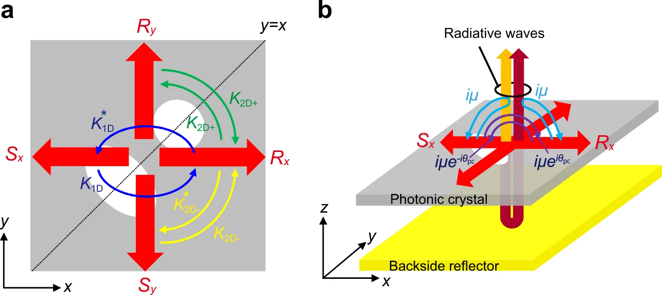
Hermitian and non-Hermitian optical couplings inside PCSELs. a Hermitian couplings between the four fundamental waves $(R_x, S_x, R_y, S_y)$ inside a PCSEL. b Non-Hermitian couplings via radiated waves, where a backside reflector is used for the control of the non-Hermitian coupling coefficient $i/mu$.
Let us start from photonic crystal with a square lattice of air holes which are not so symmetrical in a multilayer dielectric slab. The four basic waves (Rx, Sx, Ry, Sy) which play main role in photonic crystal are in the same direction as the primitive vectors of the cell. They represent the amplitudes of waves propagating in their direction.
Theory Derivation
Consider transverse electric (TE) polarization in photonic crystal, because it is normally laser mode in MQW structure.
∇×∇×E(r)=k02n~2(r)E(r)
Where Eis electric field, k0 is free-space wave vector, n~ is complex refractive index and ris position vector. k02n~2(r)≃k02n2(r)+2ik0n0(z)α~(z), where n2(r) is periodic, n0(z) is the average refractive index of the material at z, and α~(z) is gain (>0) or loss (<0) in each region. Because photonic crystal is periodic structure, it is obvious the electric field is also periodic. By using Bloch’s theorem, E(r)=(Ex(r),Ey(r),0) can be expanded as
Where β0 is propagation constant and in photonic crystal β0=2π/a (a is lattice constant), and ξm,n(z) is the high-order Fourier coefficient term. And then, combining the above three formulas, … (See Ref. 3, page 57). We have retained the spatial and spatial derivative terms of Ex and Ey with respect to x and y, so we can use them in a finite system in next section. So, We now can obtain four basic waves in
Where Θ0(z) is the field profiles in the z-direction of four basic waves, which is the same as the field profile of the fundamental guided mode for a multilayer structure with no periodic structure. The profile Θ0(z) for basic waves can be determined by the waveguide mode profile,
∂z∂2Θ0+[ϵ0(z)k2−β2]Θ0=0
Where β is the propagation constant, which satisfies β≃β0 under condition of Γ point resonance. β and Θ(z) can be calculated by employing the transfer matrix method. Then, normalize Θ(z) as ∫−∞∞∣Θ(z)∣2dz=1. Now, we can calculate four basic waves. Here, take Rx as an example. Combine them and neglected the second spatial derivative terms because of the slow variation of Rx compared to eiβ0x, we can get
Here, CHermitian, Cnon−Hermitian, Cnon−Γ is only related to photonic crystal materials and structures (see Theory derivation). And by solving matrix eigenvalues we can get δ and α, where δ=(β2−β02)/2β0≃β−β0=neff(ω−ω0)/c. neff is the effective refractive index for the fundamental guided mode and α is the mode loss.
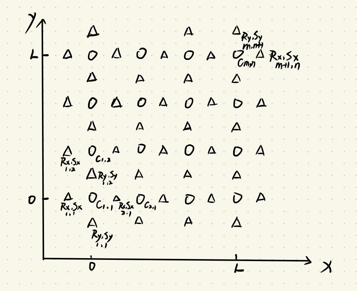
Circles mean the known coupled matrix C, triangle mean the unknown field components are updated using the finite-difference schemeThe boundary condition of a finite photonic crystal (with a side length L) can be defined as
Rx(0,y)=Sx(L,y)=Ry(x,0)=Sy(x,L)=0
In Ref. 3, with the lattice constant a=295 nm, and the device length L=70 μm, the laser is divided into 14 sections for which the eigenvalues (αL and δL) converge well. Finally, if we define
Here, Pstim describes the total stimulated power inside the laser structure, Pedge represents the power escaping from the edges of the laser cavity (i.e. the in-plane loss), and Prad represents the radiation power emitted from the device surface. Here, κv.i=−ℑ{2β0k04∬PCG(z,z′)Θ0(z′)Θ0∗(z)dz′dz} is closely associated with the out-of-plane coupling remains.
Time-Dependent
Consider transverse electric (TE) polarization in photonic crystal again, but this time is time-dependent:
∇×∇×E(r)=−c21∂t2∂2[n~2(r)E(r)]
Where c is the speed of light in vacuum. Then, expand this equation according to Bloch’s theorem (See Ref. 5). Finally, we obtain
Where, C is a 4 × 4 matrix that represents the direct and indirect cross-coupling of the basic waves. g(N) denotes the optical gain of the active layer, which is positive inside the gain section and negative inside the loss section (g(N)=N+[gmax/(−g0)]Ntrgmax(N−Ntr)1+ϵU1). ng is the group index of the guided mode, Γ is the optical confinement factor inside the active layer, δ is the deviation from the Bragg condition due to the carrier-induced refractive index change inside the active layer (δ=δ0+λ2πΓΔn), αin is the material loss, γ is the rate of the refractive index change (whose effect is minor) and fi (i = 1–4) is random noise due to spontaneous emission. (Ref. 6)
Conclusion
In this post, I organized the algorithm steps and briefly described the proof of 3D-CWT. However, if you need to have a detailed understanding of the derivation of CWT, Ref. 3 and Ref. 5 are sufficiently detailed. If you need the relevant code for 3D-CWT, please feel free to contact me.