使用Lumerical FDTD进行Photonic Crystal仿真

At The Start
Maybe you need to read:
- 使用Lumerical MODE进行平面平板波导仿真 - Maple’s Blog (maple367.eu.org)
- CWT in PCSEL - Maple’s Blog (maple367.eu.org)
FDTD?
FDTD is an abbreviation Finite-difference time-domain.
Finite-difference time-domain method - Wikipedia
Finite-difference time-domain (FDTD) or Yee’s method (named after the Chinese American applied mathematician Kane S. Yee, born 1934) is a numerical analysis technique used for modeling computational electrodynamics (finding approximate solutions to the associated system of differential equations). Since it is a time-domain method, FDTD solutions can cover a wide frequency range with a single simulation run, and treat nonlinear material properties in a natural way.
Layout Mode
对于980 nm波长,以以下参数进行建模:
| Material | Thickness (μm) | Refractive Index |
|---|---|---|
| Air | 0.5 | 1 |
| GaAs | 0.1 | 3.4824 |
| Al0.1GaAs | 0.36 | 3.4461 |
| Active Layer | 0.216 | 3.4 |
| Al0.4GaAs | 2.16 | 3.2449 |
| GaAs | 0.15 | 3.4824 |
注意此参数中衬底层和空气层设定为约0.5个有效波长,这是为了在边界保留足够的空间域,以避免数值求解及边界条件造成的异常反射等影响结果。
插入几何体
插入Layer structure
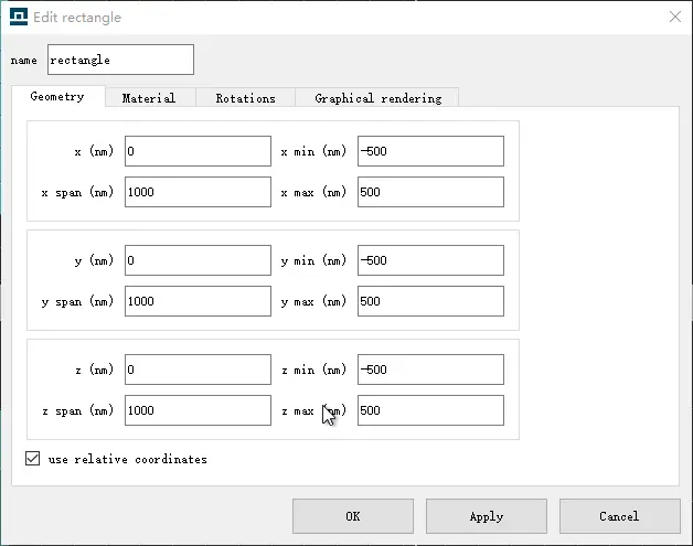
点击工具栏的Structures即可添加一个rectangle对象,右击选择Edit object,分别设置该物体的几何参数Geometry与材料参数Material与建模参数一致。比如第一层空气z max为500 nm,z min为-500 nm,然后逐层往下设置
 |  |
|---|
逐步重复此过程,完成所有几何体的添加。x及y可以随意设置,建议保持中心对齐且长宽一致。注意此处需要将最顶端的空气和最底端的GaAs额外加厚0.5μm,目的是保证几何体连续的延伸到稍后设置的PML边界中。
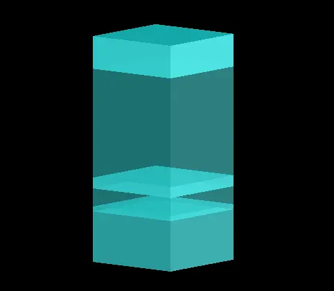
最终会得到一个类似图示的结构模型(为了便于观察,调节了显示透明度以区分,可以在物体的Graphical rendering中调节alpha实现)。
插入空气孔
在Components下拉框中选择Photonic crystals,找到Rectangular lattice PC array添加。然后就可以在Object Tree中调整它的参数,设置如下。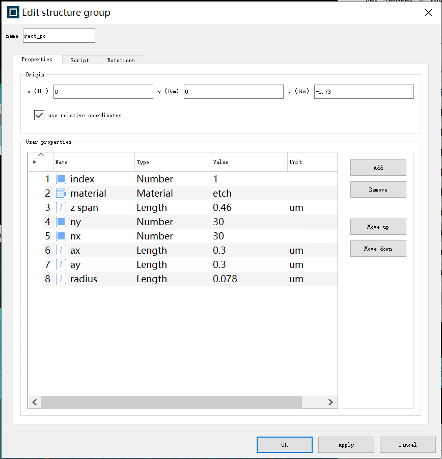
其它建模方式
Lumerical Script Language
点击工具栏Group下拉框,选择Structure。可以看到新生成了一个structure group对象,可以通过在Properties栏定义参数、Script栏输入脚本生成一组几何结构。具体脚本用法请参考Lumerical scripting language - By category – Ansys Optics。
Python API
Lumerical还支持使用Python API调用Script,进行建模及分析操作,可以将仿真与数据后处理集成。具体调用方法请参考Python API overview – Ansys Optics。
设定求解器
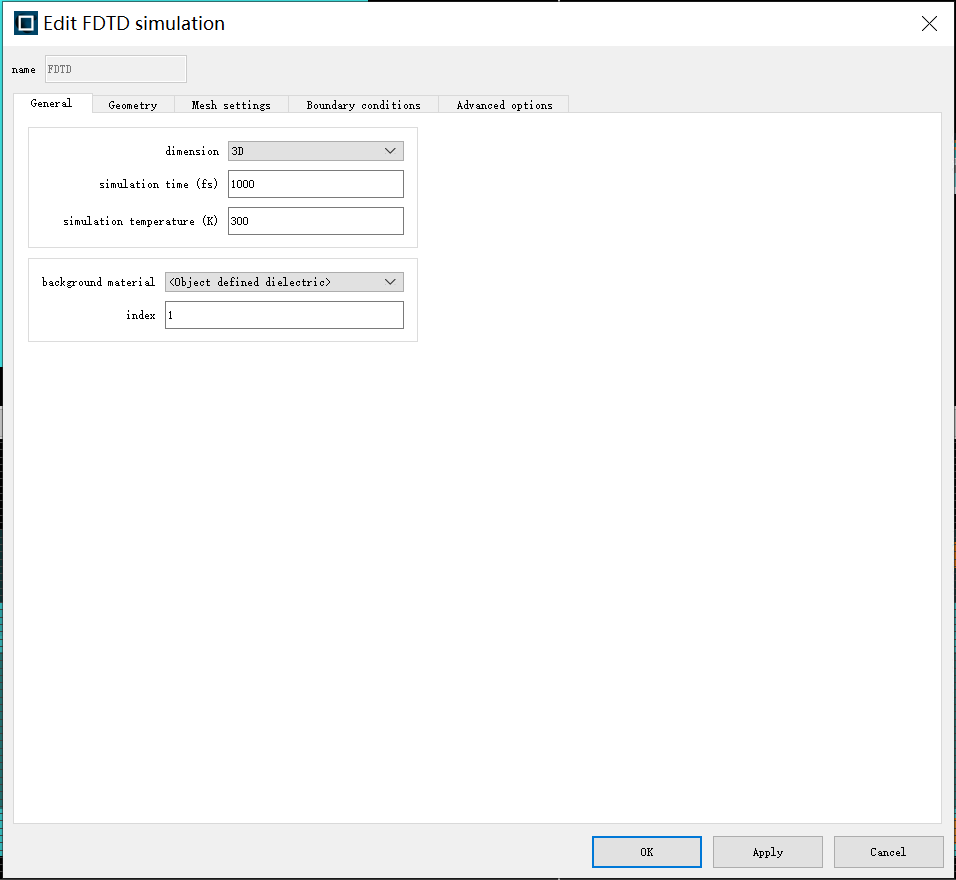
点击工具栏的Simulation下拉框,选择Region,即可创建一个FDTD对象。调整其General选项卡的dimension为3D,调整其Geometry以匹配模型大小与位置,并将Mesh settings中的mesh accuracy精度调节为3。最后设定Boundary conditions为PML。具体设置参见下图。
 | 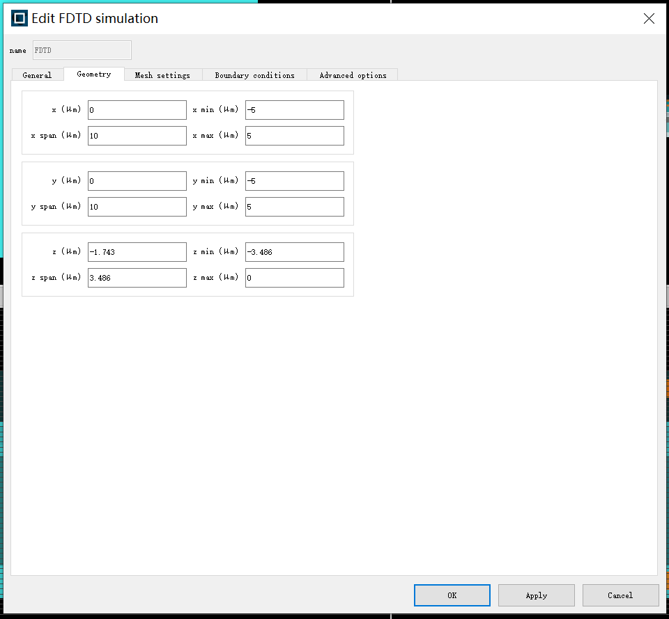 |
|---|---|
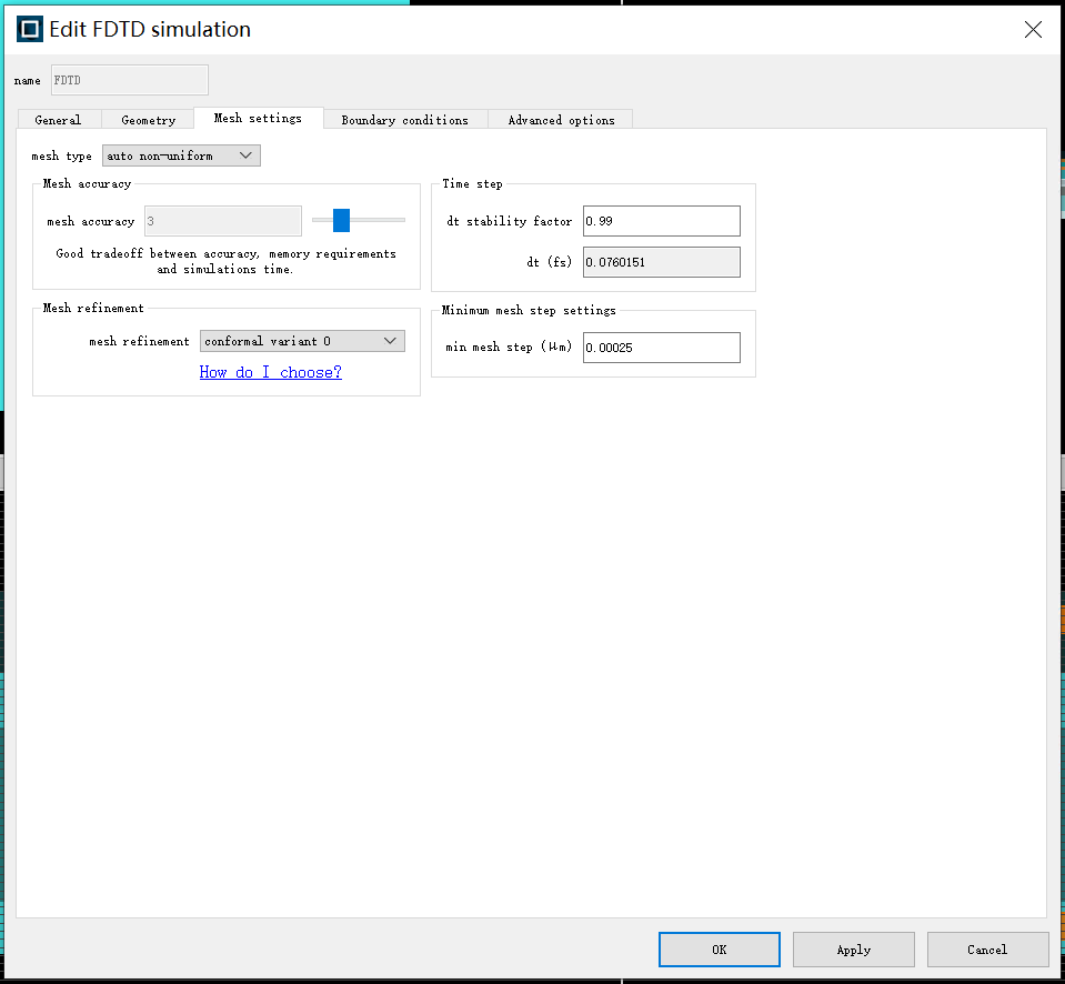 | 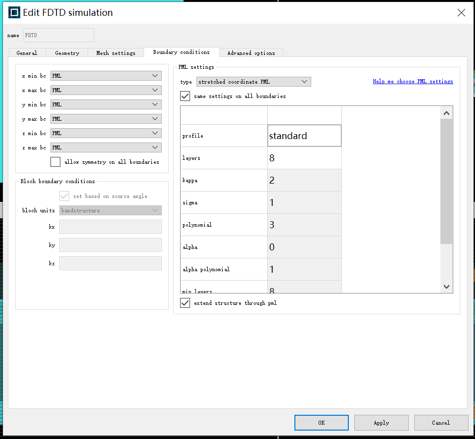 |
添加Source
由于FDTD是时域算法,所以我们需要一个初始激励,来形成电磁波。通常可以通过Source添加。这里我们使用Analysis中的More choices...的Bandstructure下的Diopole cloud添加。调整参数如下图所示,参数的说明可以在Script选项卡查看。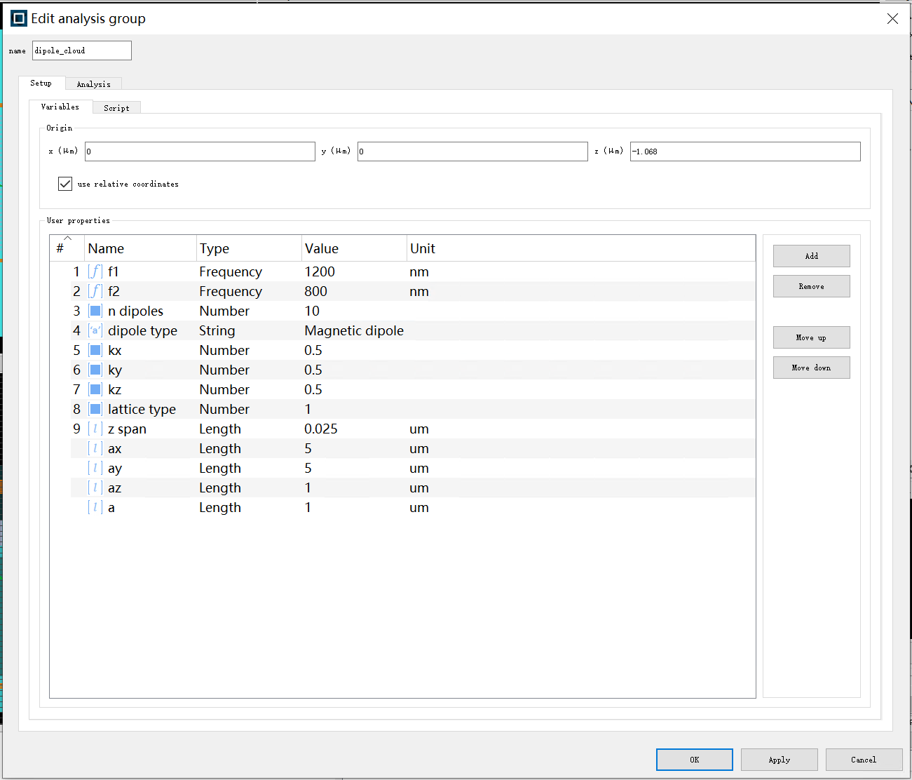
添加Monitor
我们还需要添加相应的monitor来获取我们需要的电磁场信息。这里我们选择添加Analysis下的Q analysis。调整参数如下表
| Name | Value | Unit |
|---|---|---|
| x | 0 | um |
| y | 0 | um |
| z | -0.83 | um |
| x span | 0.5 | um |
| y span | 0.5 | um |
| z span | 0.6 | um |
| nx | 3 | \ |
| ny | 6 | \ |
| nz | 6 | \ |
此外还可以在Monitor下拉选项中添加所需要的其他monitor。
运行仿真
调整Resources(可选)
在工具栏点击Resources,按需求设置。
运行
点击工具栏Run。
Analysis Mode
点击Run之后会弹出Job Manager窗口,运行完之后即可查看每个monitor的结果。方法是在Object Tree中右键相应monitor,然后Visualize直接查看结果,或者Export to ZBF导出数据后,自行处理。仿真的数据会存储在对应的仿真文件.fsp中,如果需要重新运行,将会切换到Layout Mode。此时文件中的所有结果数据都会丢失。
At The End
如果需要大量数据分析,建议使用自带的sweep功能并灵活运用Lumerical自身的script功能,或者使用Python API。
- Title: 使用Lumerical FDTD进行Photonic Crystal仿真
- Author: Maple
- Created at : 2024-12-31 11:39:46
- Updated at : 2024-12-31 13:36:47
- Link: https://www.maple367.eu.org/Optics/Simulation/使用lumerical-fdtd进行photonic-crystal仿真/
- License: This work is licensed under CC BY-NC-SA 4.0.